News
Electrical – Substation Design Calculations
Electrical – Substation Design Calculations
Protection and control analysis


| Why conduct protection and control analysis? |
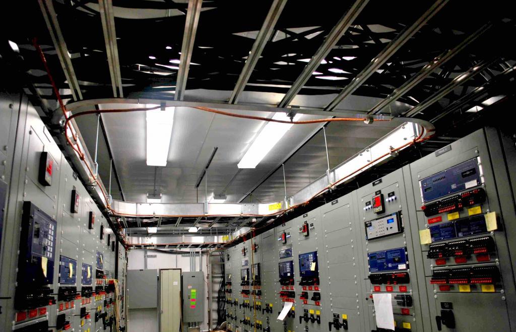
| Power substations contain expensive pieces of equipment. Some form of protection is required to prevent them from going up in smoke. Protection of modern substations is implemented using microprocessor relays.
Relays are required to: |
| Outcome of protection and control analysis |
| – Specify protection and control logic for the substation equipment. – Specify SCADA and communication system for automation, annunciation, and remote control purposes. – Create relay settings that coordinate with other relays (in the station and at remote-end). – Create relay settings that generate high-speed tripping to disconnect generators or loads (during abnormal conditions) to maintain grid stability.Results are incorporated in the following drawings: – Oneline, AC schemes, DC protection schemes, relay panel wiring drawings, SCADA and communication drawings – Control building layout – Relay panel front views |
DC system – battery calculations

| Why conduct battery calculations? |
| – Motors which operate high voltage switch and ones that charge the spring inside the circuit breaker – Microprocessor relays inside the building and inside the power equipmentall work using DC power. A battery that not only packs enough energy but also provides the discharge characteristics to operate substation equipment is needed. |
| Outcome of battery calculations |
| Specify batteries with enough amp-hour capacity to support the continuous load for 8 hours and momentary load (such as breaker and switch operation) for a minute or more. The popular battery chemistry in the industry is lead-sulphuric acid.
Specify battery charger that is capable of charging the battery. Results are incorporated in the following drawings: |
AC system – auxiliary power transformer calculations

| Why conduct auxiliary power transformer calculations? |
| Not all loads in the station rely on DC power.
The HVAC system, transformer fans, lights, cabinet heaters, lift-stations/sump pumps, battery charger, etc require AC power. |
| Outcome of auxiliary power transformer calculations |
| Specify auxiliary transformer capable of supplying the demand.
Results are incorporated in the following drawings: |
Ground grid study


| Why conduct ground grid study? |
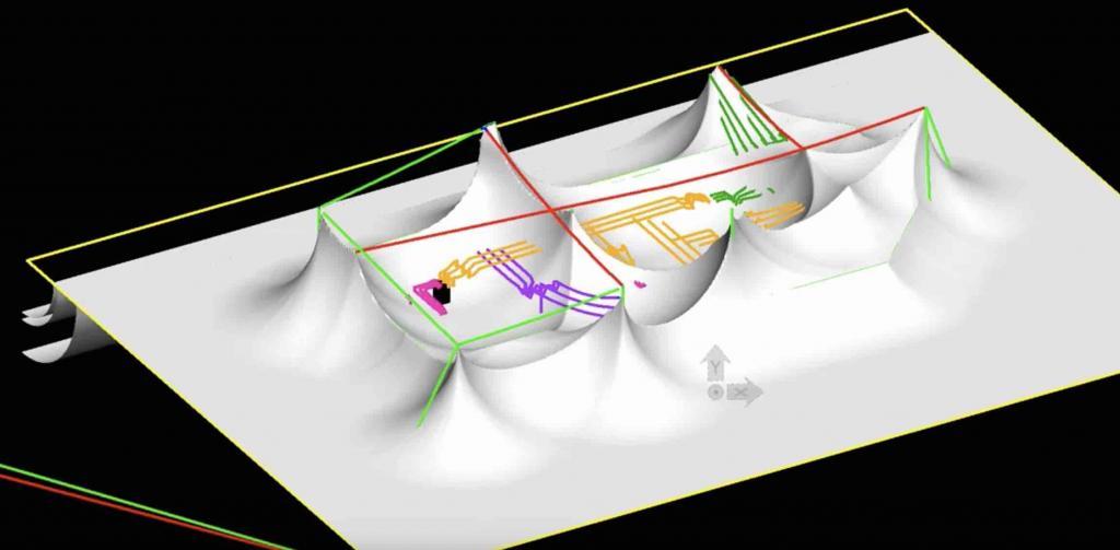
| A lightning strike on tall power transmission structures is inevitable. When this surge is buried into the earth, it needs a path to dissipate. If this path is unavailable (due to high resistivity soil, for instance) the ground potential rises at the point of contact.
This is a hazardous situation. Anyone walking in this area is subjected to an electric shock because of the potential difference developed between feet (with reference to Figure 8, one foot on red peak and the other on blue valley). This is called step potential. The same concept applies to touch potential. |
| Outcome of ground grid study |
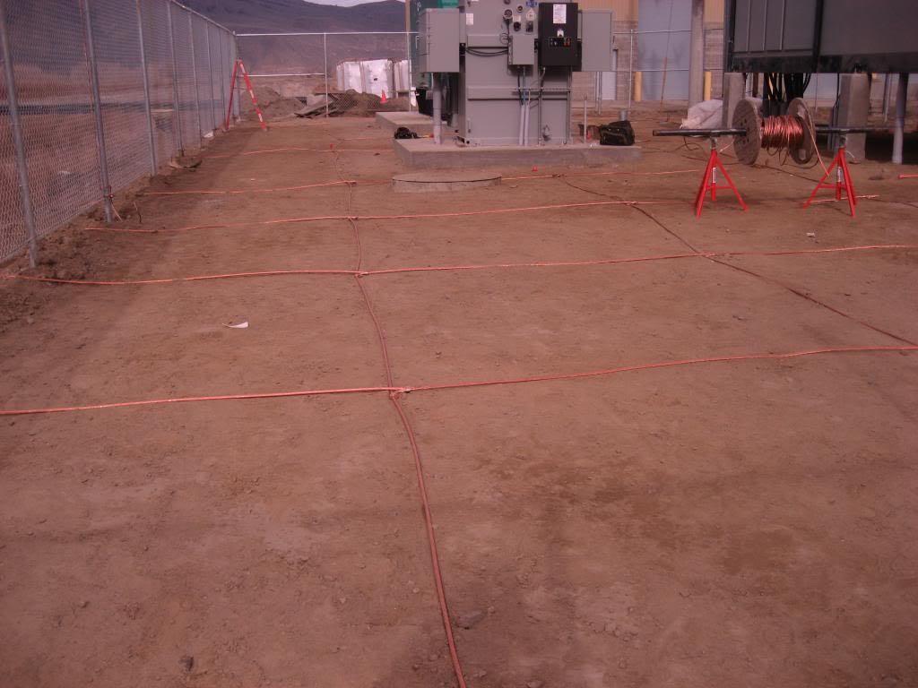
| Install mesh grounding system as shown in Figure 9 to create an equipotential surface. Drive ground rods into the earth (10′ or 20′ or 40′ as determined by the study) and tie the mesh to the rod – allowing the mesh to access low resistivity soil.
Because earthing is impacted by soil resistivity, in certain cases, the native soil needs to be replaced to get the desired results. Results are incorporated in the following drawings: |
Lightning protection calculations


| Why conduct lightning protection calculations? |
| Substations need a shield to protect itself from lightning strikes. |
| Outcome of lightning protection calculations |
| Install a combination of lightning masts and shield wires that provides adequate lightning strike coverage.
It should be noted, creating 100% coverage is impossible. Therefore a probability study is conducted to determine the likelihood of a lightning strike on the unprotected equipment. If the risk is acceptable then the coverage is reduced or not installed at all. Results are incorporated in the following drawings: |
Lighting calculations


| Why conduct lighting calculations? |
| Substation security and safety of personnel is important. A well lit area serves this purpose. |
| Outcome of lighting calculations |
| The height and angle of LED head that provides the required foot-candles of light intensity are calculated.
Results are incorporated in the following drawings: |
Voltage drop calculations


| Why conduct voltage drop calculations? |
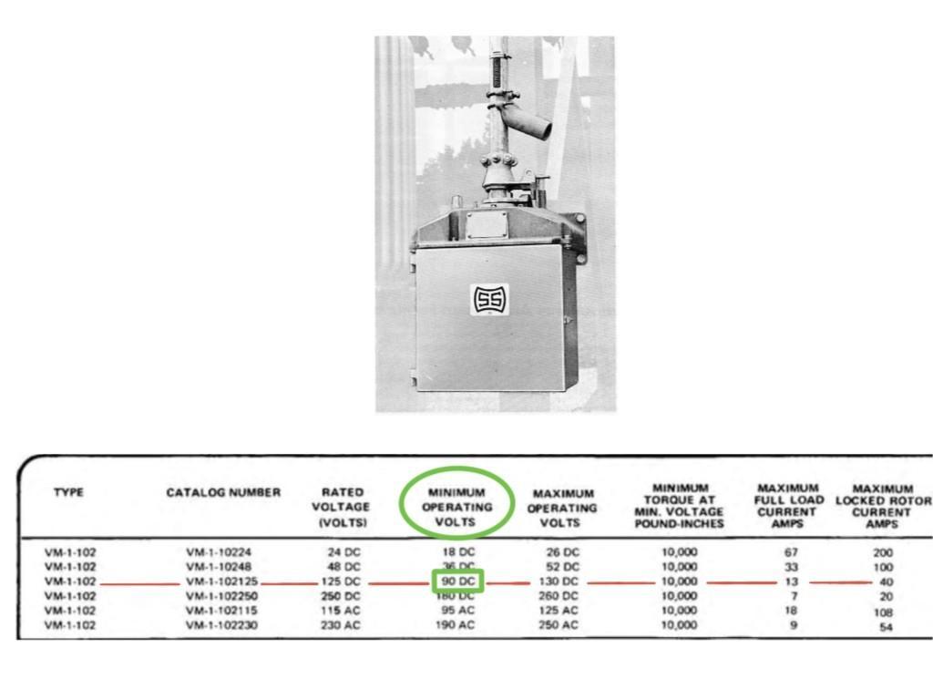
| Motors or coils that operate massive substation equipment require a certainminimum voltage to operate. Failure to do so renders it inoperable. |
| Outcome of voltage drop calculations |
| Determine wire size (1/0AWG or #2 gauge or #6 gauge etc.) such that voltage developed at the receiving end is within equipment working limits.
Results are incorporated in the following drawings: |
Conduit fill calculations

| Why conduct conduit fill calculations |
| This is fairly straightforward. Pulling more wires than what is possible will break below grade PVC conduits especially at the bends. |
| Outcome of conduit fill calculations |
| Specify the quantity of wires that can be pulled.
Install a combination of handholes or manholes or cable troughs to make cable pulling easy. Results are incorporated in the following drawings: |