News
System Planning – Power Substation Design Calculations
System Planning
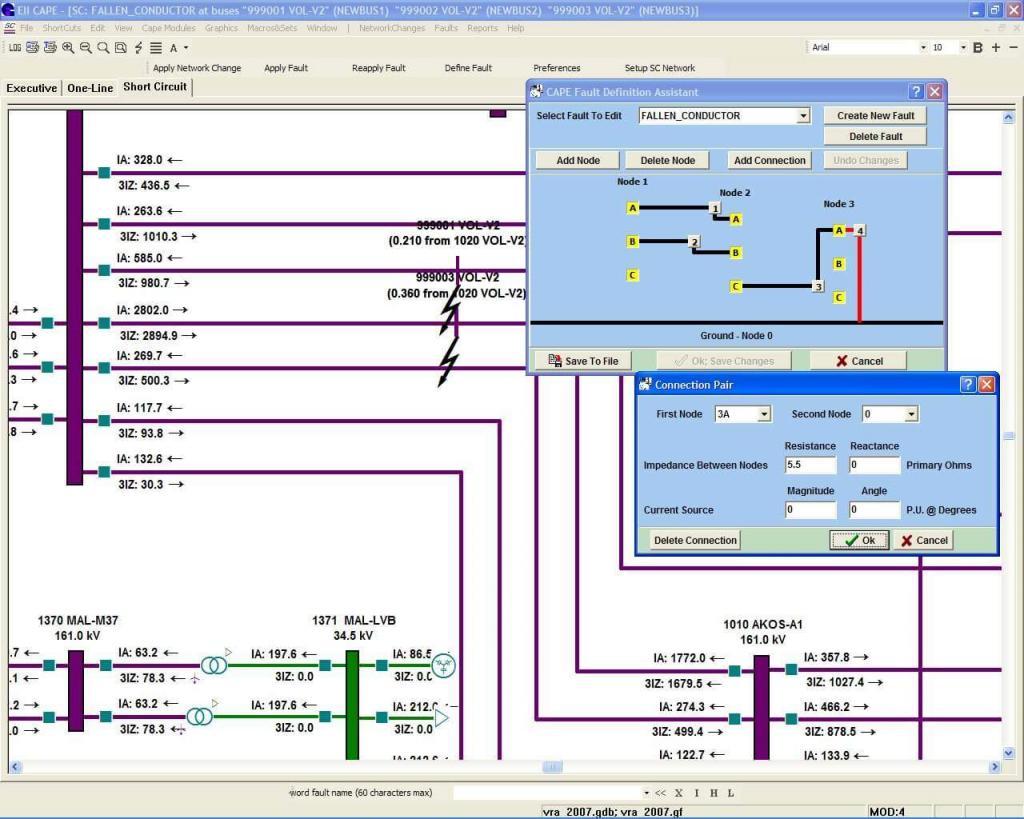
Short-circuit study

| Why conduct short-circuit study? |
| Hundreds, if not thousands, of generators are tied to the power grid. Rotating loads like induction motors are integrated as well. When a short-circuit occurs – generators pump current into the fault. – motors (which store energy in the magnetic field) backfeed into the fault. Under-rated equipment subjected to this sudden current in-rush may catastrophically fail. |
| Outcome of short-circuit study |
| The study furnishes momentary and interrupting fault current magnitudes along with impedance to the fault location (either in symmetrical components X1-X0 or X/R ratio)
You should use the results to |
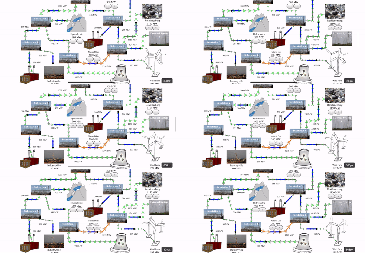
Load flow study

| Why conduct load flow study? |
| The grid operates in equilibrium. When load increases, the equilibrium shifts to a new high, with generators ramping up to keep up. This increase in power (consequently the continuous current) overheats underrated equipment and causes the insulation to deteriorate or fail. Furthermore, some amount of power is lost as heat on the transmission lines. This results in a voltage drop at the receiving end of the line. |
| Outcome of load flow study |
| The study furnishes voltage drop, continuous current, and power factor at different nodes in the grid.
You should use the results to Note: Minimum ratings are also standardized by the Regional Transmission Operator (RTO). For example, this design criteria document for transmission owners (under PJM) mandates continuous current for line terminal equipment. If the load flow study prescribes a lower rating, you should discard the results in favor of RTO requirements. |
Insulation coordination study

| Why conduct insulation coordination study? |
| The power grid is subjected to lightning strikes and temporary over-voltages. A lightning strike occasionally carries greater than 1 million-volts, 100 kilo-amps, and 20 giga-joules of energy.
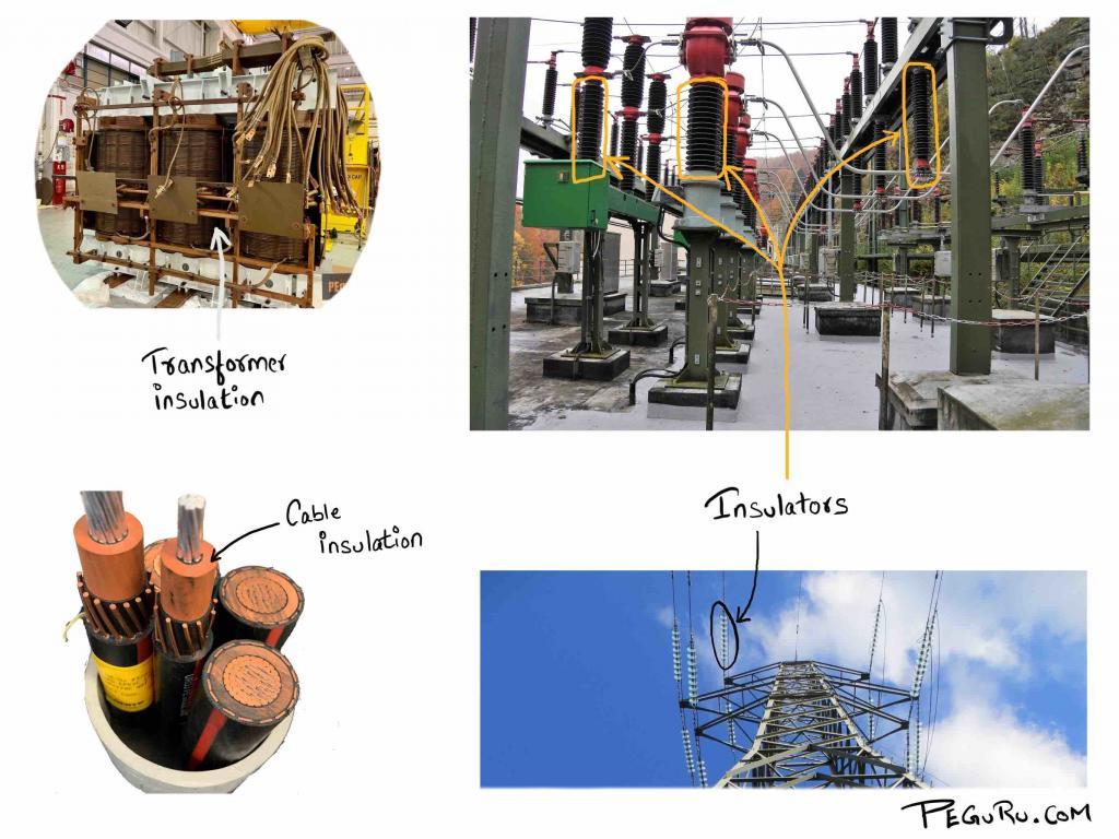
How “beefy” should the insulation be to survive this? You could spend a lot and over insulate or, when the budget is a concern (which is typically the case), build a station with reduced insulation. |
| Outcome of insulation coordination study |
| Choose standardized BIL rating (Basic lightning impulse Insulation Level) for the substation from IEEE 1313.1 standard. If you are choosing lower insulation level, pay close attention to the ratings of surge arrester and its install location.
Results are incorporated in the following drawings: Note: There are no formulas to calculate BIL. It has been established based on experience and lab tests. At 345kV and above voltage, a switching surge has highervoltage magnitude than lightning. Choose BSL levels from the same standard for this voltage class. |